Installing an Icom ID-5100 in a 2017 GMC Canyon Denali
Introduction
This post documents how and where I installed my Icom ID-5100 into my brand new 2017 GMC Canyon Denali. My goal was a very clean, professional looking install with no wires cluttering up the interior of my truck. I’ve always been of the mind that if you are going to do something, do it right. This requires you to drill holes, quite a few of them.
Planning:
I spent a lot of time figuring out exactly where each component of the radio was going to go. I then spent considerable time figuring out how all of the wires would travel, unseen throughout the truck. I took apart sections of the truck to see how I could get everything where I wanted it to go. A set of trim removal tools are worth their weight in gold for this! This process took me two months. I’m a measure twice, cut once kind of guy. It is also a brand new truck and I did not want to get half way through my install only to figure out my plan was not feasible. This install will require you to drill holes. There is no way around a clean install without drilling holes.
End State
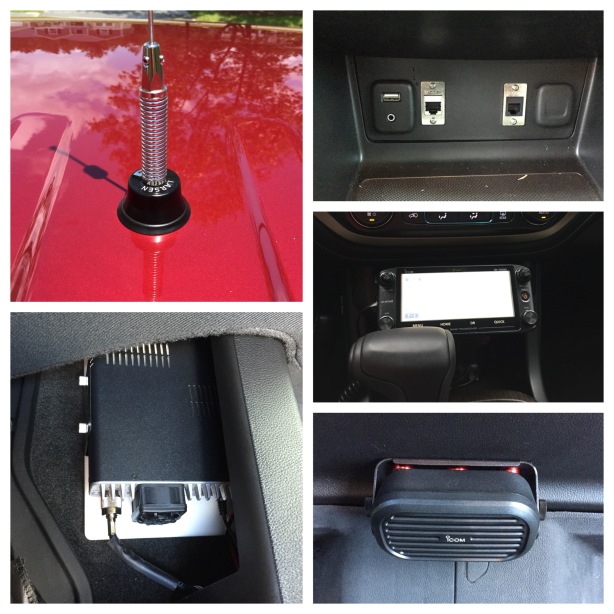
When this install is finished, the components will be in the following locations:
– Radio Body – under the rear passenger seat with easy access to the SD Card
– Antenna – center of the roof with an NMO antenna
– Control Head – in the cubby hole forward of the gear shift. The RJ12 cable will be plugged into a custom keystone installed next to the cigarette lighter.
– Microphone – Attached to the left side of the front console face plate. The microphone is plugged into a custom RJ45 Keystone installed next to the USB port and aux port.
– External Speaker – underneath and in front of the rear seat.
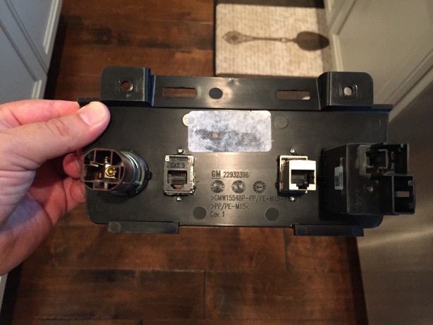
Radio Body
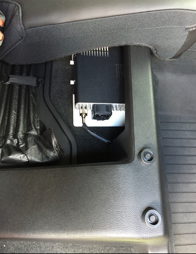
ID-5100 Radio body under rear passenger seat.
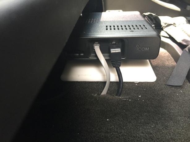
All of your wires converge on the radio body, so it’s placement is crucial to success. My radio body is located under the rear passenger side seat. I bought a cheap 6″ x 10″ cutting board and mounted the radio mounting bracket to the cutting board. I cut about 2 inches off with a skill saw so it was the length of the radio body. I applied outdoor Velcro on the bottom of the cutting board to prevent slipping. It is perfectly hidden, secure, and close to a cut-out in the carpet to enable easy access to wires coming out from underneath the carpet. I chose the passenger side for the radio body because it took up less storage space and would not be in my way when accessing the storage from the rear driver side.
Control Cable and Microphone Cable
Small slit in the carpet to allow the control cable and microphone cable to travel underneath the carpet and center console.
I used a razor and cut a slit in the carpet just below and in front of the microphone and control cable connection sockets on the radio body. I fished a coat hanger through the slit and it came out under the center console. I tied two long pieces of paraccord to the coat hanger and pulled them back through the slot. I tied the microphone cable and the control cable to each of the pieces of paracord. I pulled the microphone cable through and then the control cable. Both cables run along the driver side center console, the panel is easily removed by moving the seat all the way to the rear and pulling outward to pop the clips. I zip tied the excess cable and then ran the ends up and around until they came out behind the area where they attach to the USB and 12V charger plate.
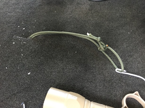
Paracord pulled underneath carpet. Tie control head and microphone cable to each piece of paranoid and pull through.
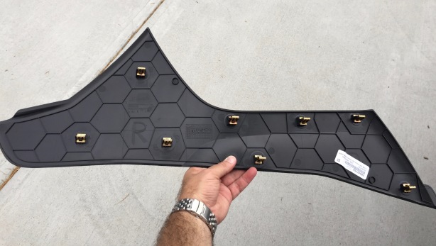
8 clips on the front center console panel. This shows the right (passenger) side; the driver side is identical.
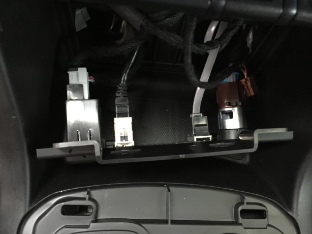
RJ45 and RJ12 Keystones
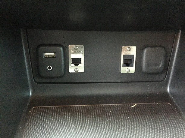
RJ45 and RJ12 Jacks for Microphone and Control Head Cable
Back of the USB and 12V panel. Both the USB and 12V panel are easily removed.
I used a Dremel tool to carve holes for the keystone mounting plates. I used a carpenters square to get them straight. I took my time shaving off material a little at a time and test fitting until they were straight and aligned. I drilled pilot holes for the screws and then screwed the keystones into the panel. I connected the microphone and control cable, and then put the dash back together. The keystone panel mounts I bought on eBay came with RJ45 keystones, so I had to purchase an RJ12 keystone off of Amazon for the control cable.
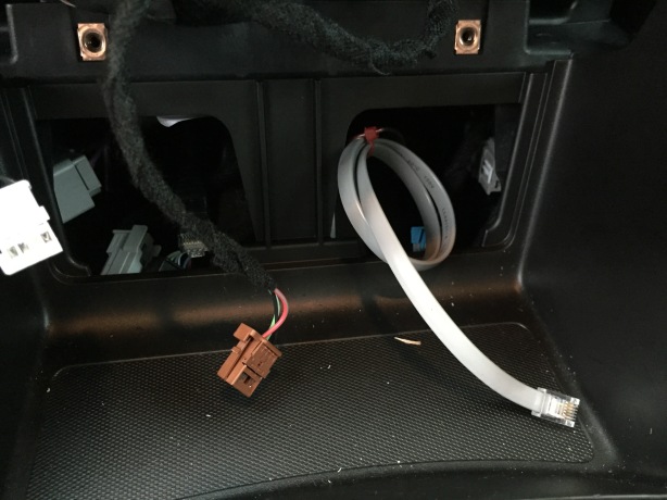
Opening behind the panel mount showing where the control cable and microphone come out behind the USB and 12V jacks.
Back side showing microphone and control cables attached to rear side of the RJ45 and RJ12 keystones. The bottom of the picture is the gear shift area with the wood cover removed.
Power Lines
I used 12 gauge wire, and 30 amp Anderson PowerPoles for my power line. I drilled a 1/2″ hole in the firewall where the clutch would have gone on a manual transmission. I installed a cable gland to pass the wires through. I attached the fused positive ring connector to the accessory panel in front of the battery and the fused negative ring connector directly to the battery. Both wires were terminated with an Anderson Powerpole. I ran my power line through the firewall, down along the wire channel on the driver side, underneath the carpet to the passenger side, and out of the carpet to the back of the cubby hole in the rear storage compartment. I terminated the wires with Anderson Powerpoles.
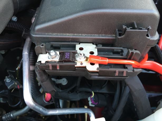
Positive ring connector connected to the power accessory area in front and to the left of the battery.
Antenna
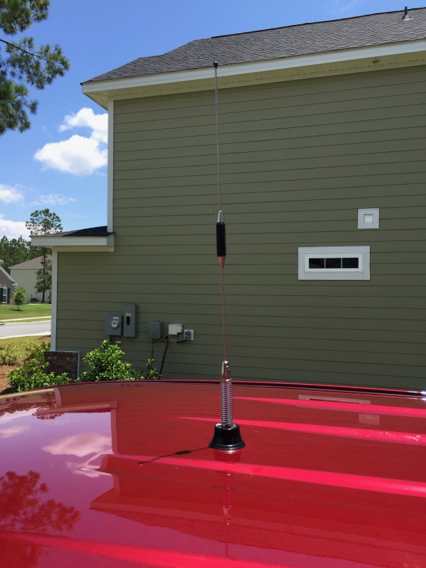
Larsen NMO 2/70SH dual-band antenna. An NMO antenna is the only way to go for a clean install and the best performance.
Installing the antenna was the scariest part of the install. Luckily, the Canyon has grooves on the roof making it easy to find the center of the roof. I covered a large area in blue painters tape then measured and marked the centerline. I then placed the antenna on the roof, along the centerline to determine where I wanted to permanently place it. I double checked under the roof liner to ensure I wasn’t sitting under a cross-brace. I did not remove the entire roof liner. I removed the rear dome light and stuffed some socks on either side of the drill site to ensure I did not drill through the liner. I used nail and a hammer to mark the exact center and to provide a dent to prevent my drill bit from slipping. I drilled a pilot hole with a 5/64″ drill bit. I then used a step bit to make to make 3/8″ hole. I then inserted the bolt of my Greenlee 3/4″ chassis punch and screwed the blade end on the bolt. I needed help on this. I had my son hold the bolt in place and then reached inside and screwed the blade on until it was seated against the roof. I then used a crescent wrench to tighten the bolt and punch a perfect hole. It cut clean through the roof and the painters tape without issue.
I then fed the coax through the hole and down the rear, passenger-side pillar, along the wire channel, under the carpet, and out of the hole in the carpet where the support beam for the rear seat storage is bolted to the floor. I cut some of the excess and then crimped a PL-239 connector on the end.
I then removed the painters tape from the roof and locked down the NMO mount with my crescent wrench and a pair of needle nose pliers.
One thing to note, my SWR was kind of high when I tested it. I dropped the whip all the way down into the spring and that fixed my SWR problem. I ended up with an SWR of 1.01 on 146.5 MHz and 1.12 on 440MHz. I did not have to cut it. I was pretty happy with these readings.
Control Head
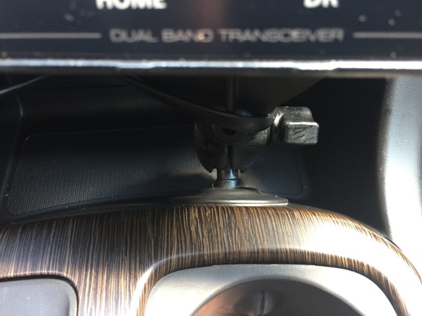
Ram Mount Flex Adhesive attached to the front of the gear shift. I offset it in front of the cup holder to allow me access to some of the cubby hole space.
I used a Ram Mount Flex adhesive for the base of the control head mount. It is applied to the smooth surface at the front of the gear shift column. It fits perfectly and is very secure. Don’t try and apply it to the bottom of the cubby hole in front of the gear shift. It will peel off. Trust me on this as that was the first place I applied it. I intentionally placed the mount in front of the cup holder to provide me some access to the storage area in the cubby hole. Additionally it prevents my hand from hitting the control head when I grab the gear shift.
I attached a small Ram Mount collar to the flex mount and then attached the RAM Curved Yoke Mount Plate to the arm. This arm brings the control head forward of the buttons on the center console and raises it up couple of inches for a perfect viewing angle.
I bought a 12″ 6P6C straight through cable with RJ12 connections on both sides to connect the control head to the RJ12 panel mount in the dash. Got it on Amazon. Worked perfectly.
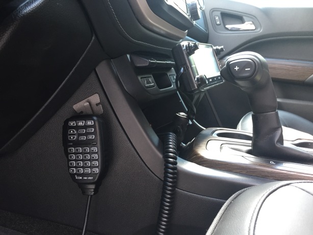
Control head and microphone attached. Everything is clean and out of the way while remaining easily accessible to the driver.
Microphone
As seen in the previous picture, I attached the microphone hook on the driver side center column. This is a great location because the microphone remains easily accessible and the cord lays flat and does not touch my legs or inhibit ingress or egress of the vehicle.
External Speaker
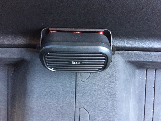
Icom SP-35 mounted just above the center column.
I mounted an Icom SP-35 underneath the rear seat. The inside of the rear seat storage frame has ridges, so I chose not to use washers. Instead I bought a piece of 3/4″ x 1/16″ x 48″ aluminum. I cut a piece the same length as the SP-35 mounting bracket. I then marked the centerline of the aluminum and drilled three holes for the left, center, and right side holes in the mounting bracket. This would enable me to mount the speaker perfectly centered under the seat and perfectly parallel to the floor. I used the speaker mounting bracket as a template to mark where I was going to drill holes through plastic storage bin under the rear seat. I ensured I had the center hole on the mounting bracket in the dead center. I marked the hole with a silver sharpie, drilled the hole and then loosely attached the bracket. I used a small level to get the bracket level, marked the holes with a silver sharpie, and then drilled the remaining two holes. I used fender washers with 6mm bolts. I recommend you use a smaller width bolt as the 6mm bolts leave no wiggle room, which meant my holes had to be perfect. Took me three tries; I’m glad I had extra aluminum. I drilled another hole to pass the speaker wire into the storage area. I wrapped the speaker wire with tech flex, routed through the hole and to the back of the radio.
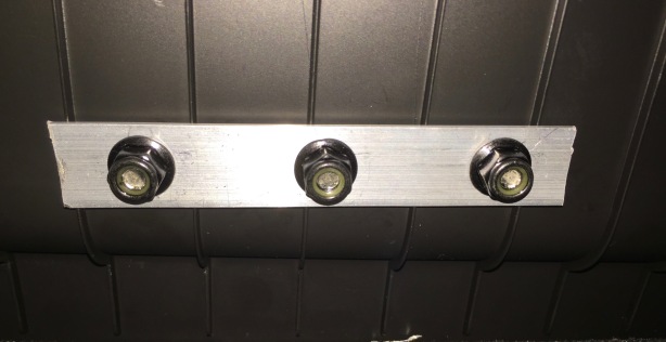
Aluminum plate instead of washers due to the ridges on the back of the storage area.
Conclusion
This was a fun install. It took me two days to complete. I took my time; measured twice and cut once. I am extremely happy with the results and am quite proud of myself as this was the first time I did any of this. I hope this write up helps and provides some inspiration for your own install.
Links to items used in this install
RAM-B-125BU RAM Curved Yoke Mount Plate
Ram Mount Flex Adhesive Base with 1-Inch Ball
RiteAV Black RJ11/RJ12 Phone Keystone Jack Female to Female
Ergo Series – Essential Kitchen 6″ x 10″ x 1/2″ Cutting Board
VELCRO Brand – Extreme Outdoor – 4″ x 2″ Strips, 2 Sets – Black
JDMSPEED 20 Pcs Red CNC Billet Aluminum Fender Washer Engine Bay Dress Up Kit

Very nice job! Also very much like what I need to do for my FTM-400. Thanks for all the pictures – it’s alot less scary when you know what you’re getting into. 73 KD6AKC
LikeLiked by 1 person
How did you pass the power wires outside the cab?
LikeLike
I drilled a hole through the firewall, using a step-bit. Location is where the clutch would pass through the firewall. There is an odd shaped foam cutout. Pull it out and drill the hole.
LikeLike
How did you get the plastic piece out that you used for the RJ45/R12? Did you just remove the side panels and then unbolt from the back? 73 W8BDM
LikeLike
No. You have to pull off the control panel for your seat heaters; it’s the piece with the small little opening that sits underneath the hazard light switch. It was a pain in the butt to take out. Use trim tools to start get it loosened. Pull straight out. I thought I was going to break it but the clips were just in really tight.
LikeLike
Thanks for this write-up, John! I’ll be drawing lots of inspiration from it when installing my tm-v71a into my new-to-me 2017 Canyon next week.
I’m a little worried about running the coax down the rear pillar. How much of a PITA was it to do, and how did you avoid messing with the side curtain airbag that’s there?
LikeLike
I pulled the side panels off and routed the cable behind/next to the curtain. Wasn’t that bad. Made sure I had plenty of slack. Take your time. You’ll be fine.
LikeLike
Very clean install! Thanks for posting it.I’m like you, measure twice (or three times), cut once and make it clean. I have a 2016 Colorado diesel I’ll be installing a Yaesu FTM-400XDR in and your install will provide some great guidance. Any problems with overheating with the body mounted under the rear seat?
LikeLike
Bill, none at all. Been back there for nearly four years, no issues at all.
LikeLike